CAD Modelling · Reverse Engineering
Jigsaw Reverse Engineering
Detailed jigsaw components recreated from physical parts through manual measurement, CAD modelling and assembly.
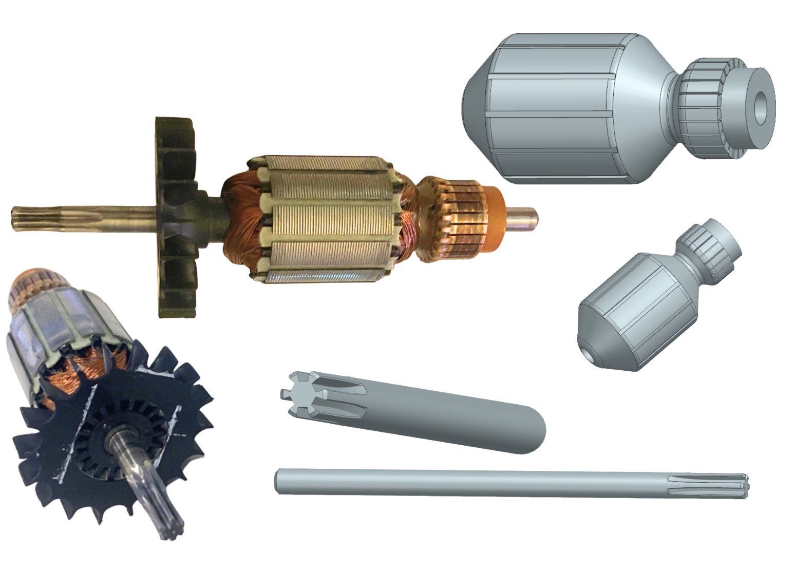
Physical jigsaw components compared with their recreated CAD models.
- Project type
- CAD Modelling · Reverse Engineering
- Course
- Advanced Computer Aided Design
- Year of study
- Year 4 of 5
- Duration
- Team
- Team of five with individual component responsibility
- My role
- Measurement, reverse engineering, CAD modelling and assembly of selected jigsaw components
- Tools & methods
- Manual measurement · Vernier caliper · Siemens NX · SOLIDWORKS · Solid modelling · Surface modelling · Parametric modelling · Top down modelling · Interpart linking · WAVE linking · Assembly modelling · Assembly constraints · Reverse engineering
- Prototype
- Detailed CAD components prepared for a shared jigsaw assembly
The challenge
The project involved disassembling a jigsaw and recreating its components as accurate digital models. The completed parts would later be combined into a shared CAD assembly.
Several of the components could not be captured through 3D scanning. Many surfaces were too reflective, while the protective visor was transparent. The parts therefore had to be measured manually using a vernier caliper and recreated from the collected dimensions.
My responsibility
Each group member was responsible for modelling a selection of components. My parts included the fan, rotor, shaft, screws, nut, blade and protective visor.
The components varied considerably in complexity. Some could be created using familiar solid modelling tools, while others required new workflows, more detailed geometry and repeated adjustments.
Fan development
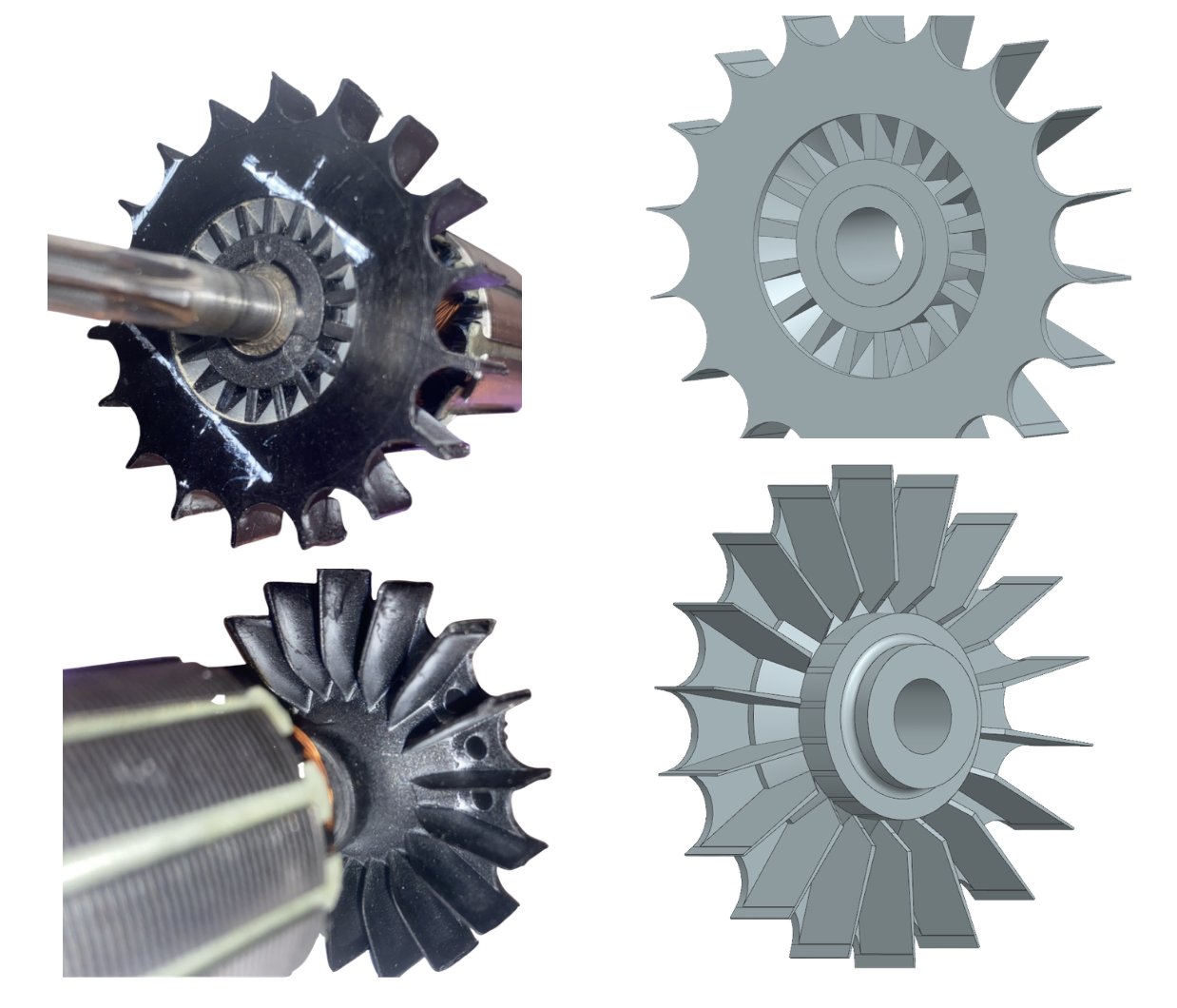
The fan was one of the most time consuming components to recreate. The main challenge was matching the shape and angle of the blades to the physical part.
I combined several modelling tools and tested different approaches to create the blade geometry. The small angled surfaces on the front also required careful adjustment to resemble the original component.
Rotor, shaft and smaller components
The rotor was relatively straightforward to model at its basic level, so I chose to focus the available time on the components that required more complex geometry.
The shaft included machined grooves along its surface. My first attempt using a standard extrusion did not produce the correct result. I therefore changed the method and used a swept form that was subtracted from the shaft.
The screw heads also required a high level of detail. During this work I discovered additional settings in the extrusion tool, including an angle option that allowed me to create a tapered opening in the screw head.
The blade was modelled in SOLIDWORKS, which was new to me. The tooth pattern required precision, and when the duplication tools did not work as expected, I created the teeth individually.
Protective visor
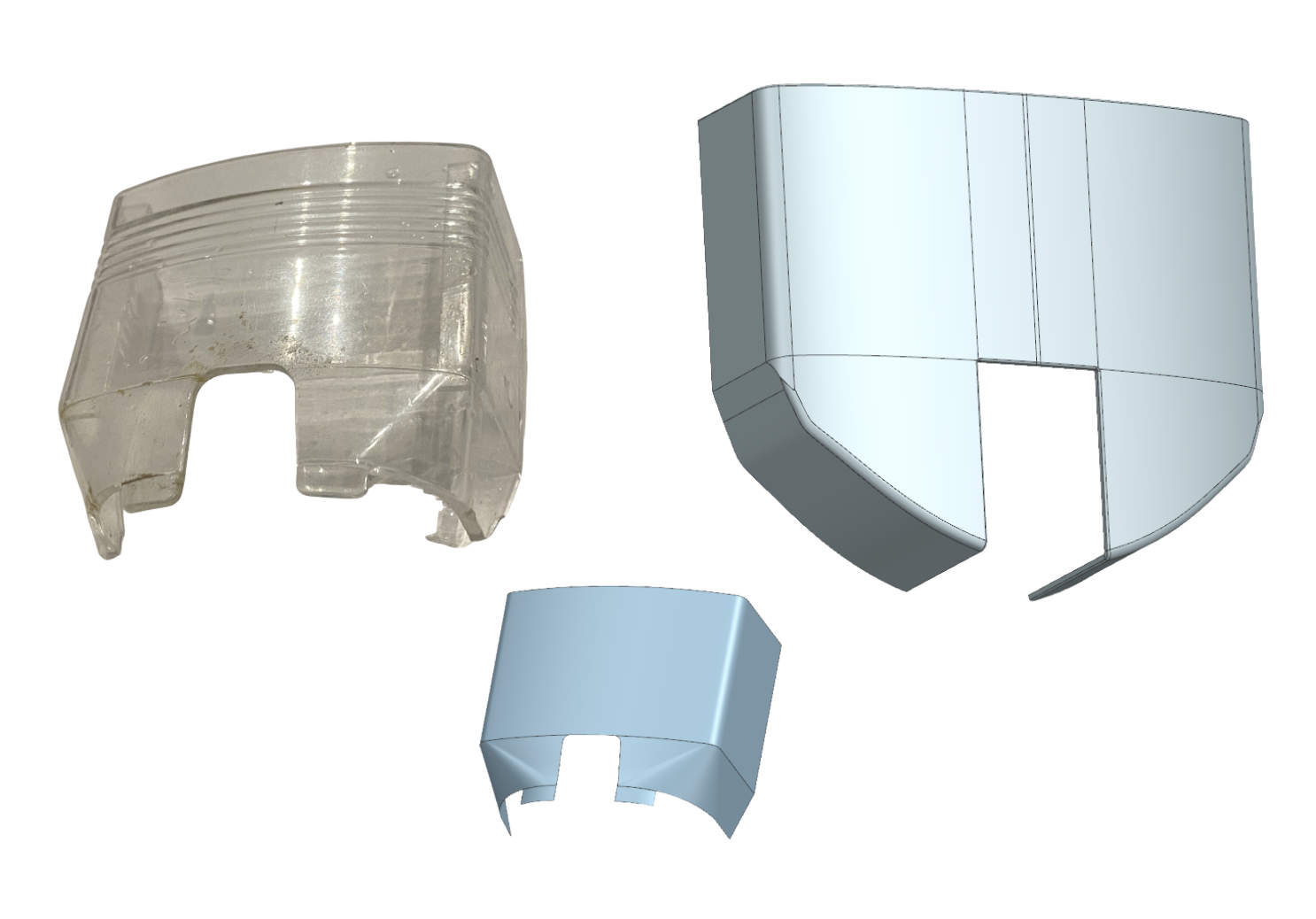
The protective visor was the final and most challenging component I modelled. I created two versions during the project.
The first version was based directly on the original physical component. Once the exterior geometry of the jigsaw had been completed, the visor needed to be adjusted so that it matched the new surrounding surfaces. The later version was therefore adapted to fit the completed outer assembly.
I first attempted to build the visor using exact modelling, but later changed to surface modelling. The method worked, although I made the process more complicated than necessary. A simpler approach would have been to create one continuous outer surface and then trim the required openings and details.
Assembled result
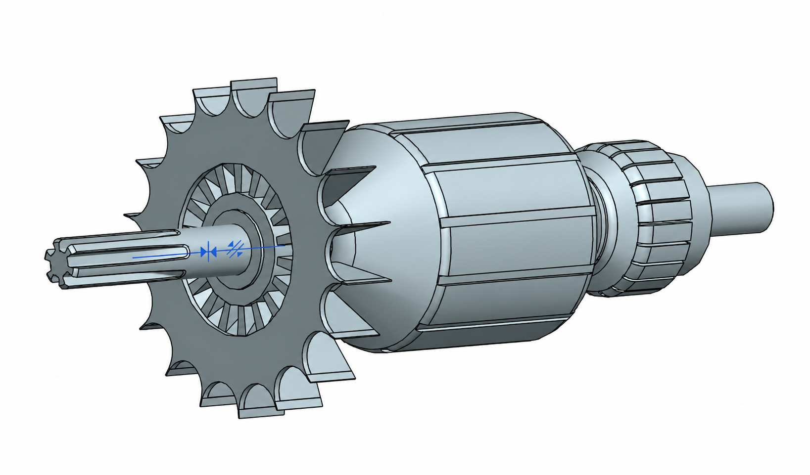
In addition to modelling the individual components separately, I also assembled the parts to show how they fit together as a complete reverse engineered result. This assembly helped communicate the overall structure and relationship between the components.
Assembly structure and linked geometry
The components needed to work not only as individual models but also as parts of a structured shared assembly. The project therefore required a clear top down approach, carefully planned assembly constraints and relationships between neighbouring components.
I worked with interpart linking and WAVE linking in Siemens NX to reference geometry between components. This allowed selected parts to be developed and updated in relation to the surrounding assembly rather than being modelled entirely in isolation.
The protective visor is a clear example of this. My first version was based on measurements from the original physical part. Once the exterior geometry of the jigsaw had been completed, I created a revised visor that followed the updated surrounding surfaces and fitted the shared assembly more accurately.
The work helped me understand the importance of a well structured assembly, stable constraints and parametric relationships. A carefully planned model structure makes later changes easier to manage and reduces the need to rebuild components manually.
Key learnings
- Physical measurements require careful interpretation before they can become usable CAD geometry.
- Changing modelling methods can be more effective than repeatedly forcing an approach that does not work.
- Individual components must be developed in relation to the complete assembly, not only as separate parts.